Additive Manufacturing
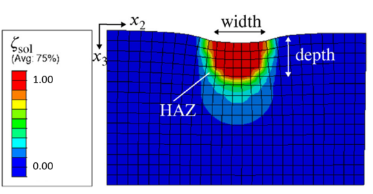
Laser powder bed fusion (L-PBF) and laser direct energy deposition (L-DED) are cutting-edge additive manufacturing (AM) techniques enabling the layer-wise production of components by selectively melting metallic particles with a laser beam. This offers vast design possibilities but presents challenges such as defects like warpage and residual stresses due to rapid heating and cooling. The research focuses on developing novel frameworks for modeling L-PBF and L-DED to enhance the understanding of the process and the prediction of the defects. This is realised by employing thermodynamically consistent material models and multiscale approaches in [1] to efficiently simulate complete parts.
[1] I. Noll, L. Koppka, T. Bartel, A. Menzel: A micromechanically motivated multiscale approach for residual distortion in laser powder bed fusion processes, Additive Manufacturing, 60(Part B), 103277, 2022, 10.1016/j.addma.2022.103277, Open Access.
Contact: Isabelle Noll
Forming Technology
Forward rod extrusion
Forward extrusion is a metal forming process in which a billet is forced through a die to obtain a specific cross-sectional profile. This process is widely used in industries such as automotive, aerospace and manufacturing due to its ability to achieve high strength components with excellent dimensional accuracy, improved mechanical properties and material conservation.
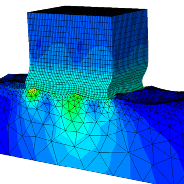
The simulation of the process, based on numerical methods such as the Finite Element Method, plays a crucial role in the design of the process. However, simulation models face a number of challenges as the manufactured part is subject to large deformations, complex process kinematics and contact interactions with the die. Particularly challenging is the integration of complex material models that account for plasticity, damage and temperature effects. The development of efficient solver structures and implementation methods is an important part of this research area.
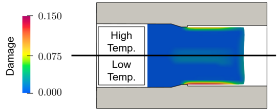
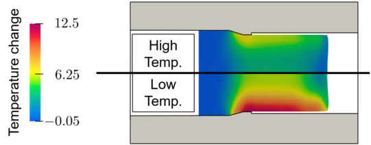
In the following application example, a gradient enhanced ductile damage model with thermomechanical coupling has been incorporated to capture the damage-temperature interaction during the process.
Contact: Lennart Sobisch
Cutting Simulations
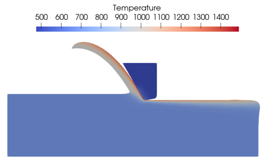
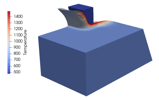
Cutting processes, such as milling and turning, are part of nearly every process chain for metal products. The design of reliable, robust, and efficient processes requires and in-depth understanding of the complex thermomechanical interactions during the chip formation. Finite element (FE) simulations, based on continuum material models of the workpiece and cutting tool, can provide valuable insights that are hard or impossible to generate experimentally. Typical applications include the prediction of forces and temperatures during the cutting process.
In the case of finishing processes, such as grinding, additional challenges arise from the large number of cutting edges and the undetermined tool geometry. One approach to this problem that was successfully applied by a joint team from the Institute of Mechanics and the Institute of Cutting Technology is a multi-scale simulation framework, based on FE simulations of the cutting at the meso-scale and a kinematic simulation to sum up the contributions of individual grains [1].
[1] T. Furlan, T. Tsagkir Dereli, N. Schmidt, D. Biermann, A. Menzel: Application of the Coupled Eulerian Lagrangian method to the prediction of single‐grain cutting forces in grinding, Proceedings in applied mathematics and mechanics 22(1), 2023. DOI: 10.1002/pamm.202200123, Open Access.
Contact: Tim Furlan
Wear
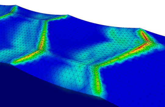
Wear is a crucial limiting factor for the lifetime of metal forming tools. In the developed wear simulation model, the surface evolution of a structured tool surface is investigated. The frictional work between contact surfaces is calculated from an Finite Element Simulation in the Abaqus software package. The wear volume is determined in the post processing of one passover using the Archard equation. Within a python script the geometry of the tool surfaces is updated to incorporate the volume loss into the subsequent forming simulations. A better understanding of wear mechanisms helps in improving tool design and durability [1].
[1] M. Schewe, H. Wilbuer, A. Menzel: Simulation of wear and effective friction properties of microstructured surfaces, Wear, 464–465, 203491, 2021, DOI: 10.1016/j.wear.2020.203491, Open Access.
Contact: Markus Schewe


